
BASIC I/O AD Hardware User Manual
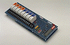
BIO4AD, BIO8AD and BIO16AD Products
| [ Home ] [ Back to Table of Contents] [ Next - Chapter 2a ][ Chapter 2b ] [ Chapter 3] [ Contact duTec ] | |
|
|
BASIC I/O AD Hardware User Manual |
Chapter 1
BIO4AD, BIO8AD and BIO16AD Products |
About BASIC I/O AD
|
Available I/O Functionality
|
Specifications
Ordering Information
Available I/O Modules |
BASIC I/O ADs are a family of small, completely self-contained, industrial grade, remote data acquisition and control systems, which exchange data with a Host computer via a serial communications link. Controlled by a Host, BASIC I/O ADs are located near the sensors and actuators. The serial link eliminates the need for expensive and noise prone field wiring between sensors and actuators, and a central control room.
In applications such as remote process monitoring, factory automation, and energy management, a variety of signals must be transmitted over long distances. Instead of requiring expensive, multi-conductor, sensor wiring for each signal, cabling costs can be reduced significantly by using BASIC I/O ADs and a single communications circuit.
One of the most useful features of the BASIC I/O AD is that in addition to gathering "raw" data, it can be instructed to perform many ranging and statistical operations upon that data before it is given to the host; thus allowing the host to spend less time manipulating numbers, and more time gathering them. Also, the BASIC I/O is able to spend more time exposed to the data which in turn allows it to base it's responses to the host on more samples of the data. The BASIC I/O AD may also be directed to manipulate outputs in specific ways to produce delayed or repetitive effects.
Each BASIC I/O AD 4, 8, or 16 position chassis will hold any mix of analog or digital, electrically isolated input or output modules which can interface to a wide variety of sensors and actuators.
BASIC I/O AD networks can service over 4000 analog and/or digital I/O lines in various combinations.
Every BASIC I/O AD is burned-in while operating in a network for a period of at least 24 hours of operation at 70°C, prior to shipment.
Every analog I/O module is tested while its operating environment temperatur is cycled over the specified operating range of 0°C to 60°C for a period of 24 hours. A computer record is maintained for every analog I/O module.
BASIC I/O ADs use duTec I/O modules to match signal requirements exactly. With a direct interface to sensors, no external signal conditioning is required. Furthermore, all duTec modules feature total electrical isolation, both module-to-logic, and module-to-module. Analog modules are available to measure:
A full range of industry standard digital modules is available for AC, DC, and dry contact inputs and outputs to hundreds of volts.
Thermocouple modules provide a cold reference junction compensation. BASIC I/O AD instructions provide linearized thermocouple and RTD sensor data. Engineering unit conversions are handled at the Host level.
On power-up, the unit self-tests for system faults and reports via a sequential displasy. Should hardware or firmware fail, an on-board hardware watchdog provides safe shutdown by turning off all outputs. Normally ON modules are available for those loads that must remain ON.
The BASIC I/O AD can be instructed to implement alarm and fail-safe states in the event of a communication failure.
The BASIC I/O AD uses a push-button and an on-board LED indicator to configure unit address, analog vs. digital map and baud rate.
The BASIC I/O AD instruction set core complies 100% with the OPTO-22 OPTOMUX serial communications protocol for remote data acquisition and control. With this speak-only-when-spoken-to protocol, which only uses ASCII printing characters, a Host transmits inquiry requests to the BASIC I/O AD to determine the status of its various process inputs. Based on the reported status, the Host makes control decidions and transmits this data, as instruction messages, to the BASIC I/O AD which uses the new decisions to make the proper changes to its various actuators. Both the Host and the communications link are essential elements in this data acquisition and process control scheme.
Originally, the protocol only allowed for all analog or all digital I/O chassis. Depending on application requirements, each BASIC I/O AD can respond to up to three different function addresses. With their abbreviations, they are:
MC - Master Unit Control function address
MD - Master Unit Digital I/O function address
MA - Master Unit Analog I/O function address
It is this multiple function addressing capability of BASIC I/O ADs that allows them to utilize, without modification, software developed for competitive products. Similarly BASIC I/O ADs can operate simultaneously on the same network with these products.
Analog Inputs:
| Input Value | Determines signal levels, with 12 bit (1 part in 4096) resolution. |
| Offsets | Input values can be software offset, with 12 bit (1 part in 4096) resolution, over the module's specified range. |
| Gain/Slope | The amplitude of input values can be software multiplied by factors ranging from 0.25 to 4.0. |
| Range Limits | The occurrence of input values falling out of user defined upper or lower limits can be flagged. |
| Minimums | The minimum level of input values can be captured. |
| Maximum | The maximum level of input values can be captured. |
| Averages | Can calculate average input amplitude for 1-65,535 samples. |
| Temperature | Provides linear temperature in °C for thermocouples, RTD and type 590 temperature probes. |
| Level Value | Can set output levels, as a fraction of the module's full scale range, and are specified with 12 bit resolution. |
| Waveforms | Can provide square, triangular, sawtooth or ramp Waveforms. Maximum and minimum amplitudes, as a fraction of the output module's full scale range, are specified with 12 bit resolution.Waveform periods are specified from 0.1 to 6,553 Seconds (about 109 minutes). All Waveforms are made up of at least 10 segments. |
| Read | Read the ON/OFF state of all inputs. |
| Edge Detection | OFF-to-ON and ON-to-OFF transitions can be detected within 1 millisecond of their occurrence. Action is reported every 10 milliseconds. |
| Pulse Widths | The duration of a single pulse or total On/Off time of consecutive pulses can be resolved to the nearest 0.01 seconds for a max total of 10.9 Min, or 46.6 Hrs with multiplied resolution. positive or negative edges initiate measurements. The time scale can be multiplied by a factor of 1-256 on a system wide basis. |
| Pulse Counting | Pulses can be counted up to a total of 65,535. To be reliably counted, pulses must have minimum and minimum ON and OFF times of 1 millisecond. Thus the maximum counting rate for a 50% duty cycle squarewave with equal ON and OFF times for a total of 2msec would be 500 HZ. |
| Note: The response time performance of digital input instructions can be limited by the delay in the input modules themselves, which can have ON plus OFF delays of up to 40 msec. | |
| Set Outputs | Can set individual or multiple outputs ON or OFF. |
| Modifiers: | |
| One Shot | Can generate ON or OFF pulse durations of up to 655.35 seconds with a resolution of 0.01 seconds. Resolution can be further multiplied by a factor of 1-256 on a system wide basis. Re-triggering is available. |
| Delayed | Can generate delayed ON or OFF outputs of up to 655.35 seconds with a resolution of 0.01 seconds. Resolution can be further multiplied by a factor of 1-256 on a system wide basis. |
| Squarewave | Can generate squarewaves with programmable ON and OFF periods. On and OFF periods have a base range from 0.01 to 2.56 seconds. Resolution can be further muliplied by a factor of 1-256 on a system wide basis. Re-triggering is available. |
| Pulse Generator | Can generate 1 to 65,535, 50% duty cycle pulses whose equal ON and OFF periods can range from 0.01 to 2.55 seconds. Resolution can be further multiplied by a factor of 1-256 on a system wide basis. |
For a complete list of I/O modules avilable from duTec see our I/O Modules Data Sheet
In addition to operating under the control of a Host, BASIC I/O AD has the ability to perform Local Control Functions without the Host. Local Control Functions (LCFs) can insure the continued safe operation of closed loop control should the Host or its communications link fail. In addition, LCF's can substantially reduce Host computational load, or communications traffic.
Once characterized, LCFs enable the BASIC I/O AD to perform control tasks without the constant involvement of a Host computer. After configuration and activation via Host instructions, LCFs take data from their input ports, perform computations and send the results to their outputs where they may drive output modules, or other BASIC I/O AD internal functions.
Utilizing LCFs to perform simple logic tasks such as analog comparisons, summations, differences, sequence generating or state machine operations eliminates the need for programmable controllers or special purpose circuitry. This capability allows more effective use of the Host computer and its communication link, because the LCFs handle the operation of the designated control function. In the meantime the Host is only required to monitor over-all system status and generate the system displays and reports. This is particularly valuable for systems using modems for communication.
Network Communications
Maximum Distance |
||
| Serial Link | Feet |
Meters |
| RS-422/485 | 5,000 |
1,524 |
Physical Characteristics
| Power | Supply | 5Vdc@<5A |
| Environment | Temperature | 0 °C - 60°C |
| Humidity | 95% non-condensing |
[ Home ] [ Back to Table of Contents] [ Next - Chapter 2a ][ Chapter 2b ] [ Chapter 3] [ Contact duTec ]
The duTec logo, and BASIC I/O AD are trademarks of duTec.
The information contained in this manual is believed to be correct.
However, duTec assumes
no responsibility for any of the circuits described herein, conveys no license
under any patent
or other right, and makes no representations that the circuits are free from
patent infringement.
duTec makes no representation or warranty that such applications will be
suitable for the use
specified without further testing or modification.
duTec general policy does not recommend the use of its products in
life support applications where
the failure or malfunction of a component may directly threaten life or injury.
It is a Condition of Sale
that the user of duTec products in life support applications+ assumes all
the risk of such use
and indemnifies duTec against all damage.
duTec
6979 Wales Road
Northwood, OH 43619
800-248-1632 or 419-666-4700
[ Home ] [ Products ] [ Data Sheets ] [ Support ] [ FAQ ] [ Sales Offices ] [ Request Catalog ] [ Contact duTec ]
Copyright 1996-2001, duTec. All rights reserved.
Please contact webmaster@dutec.net
with any questions regarding this site.