BASIC I/O AD Hardware User Manual
BIO4AD, BIO8AD and BIO16AD Products
| [ Home ] [ Table of Contents] [ Chapter 1] [ Chapter 2a ] [ Chapter 2c] [ Chapter 3] [ Contact duTec ] | |
 |
|
BASIC I/O AD Hardware User Manual |
Chapter 2b
BIO4AD, BIO8AD and BIO16AD Products |
Host to BASIC I/O AD - RS-422

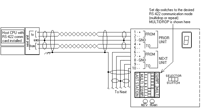
Figure 2-7 RS-422 Host to BASIC I/O AD
The wiring figure shows two individually shielded twisted pairs of AWG 24 (such as Belden 9729) with the shields connected between unit grounds. In a perfect world with no electrical noise and equal ground potentials everywhere the ground connection is not required. Not using the ground connection can lead to costly debugging.
These connections, which require the cover to be removed, are made by placing a 1/4 inch stripped wire into the openings of the wire clamp terminal block and tightening the screw. An alternative means for network connection is to use the 10-pin male connector located behind the clamp terminal block. This connector mates with Molex shell number 50-57-9005, and uses pins 16-02-0103.
In addition to the Host-to-BASIC I/O AD wiring, the installer should confirm that the Network Type switches are set in the correct positions, Multidrop, Repeat, or Last Unit.
Host to BASIC I/O AD - RS-485

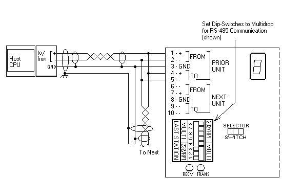
Figure 2-8 RS-485 Host to BASIC I/O AD Wiring
The wiring figure shows one shielded twisted pair of AWG 24 (such as Belden 9841 or 9341) with the shield connected between unit grounds. In a perfect world with no electrical noise and equal ground potentials everywhere the ground connection is not required. Not using the ground wire can lead to costly debugging.
These connections, which require the cover to be removed, are made by placing a 1/4 inch stripped wire into the openings of the wire clamp terminal block and tightening the screw. An alternative means for network connection is to use the 10-pin male connector located behind the clamp terminal block. This connector mates with Molex shell, number 50-57-9005, and uses pins 16-02-0103.
As shows in Figure 2-8 the + terminals of To and From and the - terminals of the To and From are connected. These connections should not be made in the clamping terminal block or Molex connector alone. A combination of the two can be used, one for jumpering and the other for the incoming and outgoing connections. Another option is to use an external terminal block or leads between the clamp terminal block and Molex connectors.
In addition to the Host-to-BASIC I/O AD wiring, the installer should confirm that the Network Type switches are set in the correct positions, Multidrop or Last Unit.
BASIC I/O AD to BASIC I/O AD - RS-422

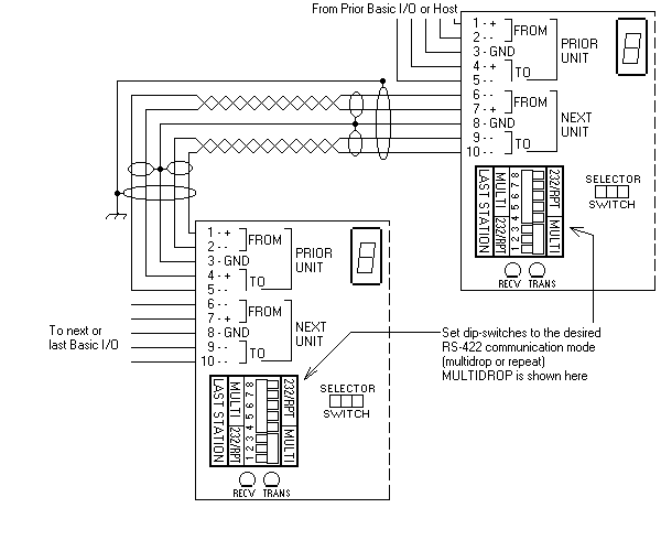
Figure 2-9 RS-422 BASIC I/O AD to BASIC I/O AD Wiring
Figure 2-9 shows two individually shielded twisted pairs of AWG 24 with an overall isolated shield (such as Belden 8162) with the internal shield connected between unit grounds. The overall isolated shield should be connected to earth ground in one place only. In a perfect world with no electrical noise and equal ground potentials everywhere, the signal ground connection would not be required. Not connecting signal ground however, frequently leads to costly debugging.
These connections, which require the cover plate to be removed, are made by placing a 1/4 inch stripped wire into the openings of the black wire clamp terminal block and tightening the screw.
An alternative means for interconnection is to use the 10-pin male connector located behind the clamp terminal block. This connector mates with Molex shell 50-57-9005, and female pins 16-02-0103.
In addition to the Host-to-BASIC I/O AD wiring, the installer should confirm that the Network Type switches are set in the correct positions, Multidrop, Repeat, or Last Unit.
BASIC I/O AD to BASIC I/O AD - RS-485

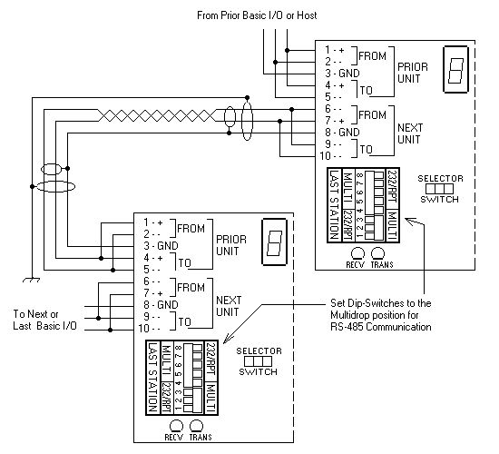
Figure 2-10 RS-485 BASIC I/O AD to BASIC I/O AD Wiring
Figure 2-10 shows one individually shielded twisted pair of AWG 24 with an overall isolated shield (such as Belden 8162) with the internal shield connected between unit grounds. The overall isolated shield should be connected to each ground in one place only. In a perfect world with no electrical noise and equal ground potentials everywhere, the signal ground connection would not be required. Not connecting signal ground however, frequently leads to costly debugging.
These connections, which require the cover plate to be removed, are made by placing a 1/4 inch stripped wire into the openings of the black wire clamp terminal block and tightening the screw.
An alternative means for interconnection is to use the 10-pin male connector located behind the clamp terminal block. This connector mates with Molex shell 50-57-9005, and female pins 16-02-0103.
In addition to the Host-to BASIC I/O AD wiring, the installer should confirm that the Network Type switches are set in the correct positions, Multidrop or Last Unit.
[ Home ] [ Table of Contents] [ Chapter 1] [ Chapter 2a ] [ Chapter 2c] [ Chapter 3] [ Contact duTec ]
The duTec logo, and BASIC I/O AD are trademarks of duTec.
The information contained in this manual is believed to be correct.
However, duTec assumes
no responsibility for any of the circuits described herein, conveys no license
under any patent
or other right, and makes no representations that the circuits are free from
patent infringement.
duTec makes no representation or warranty that such applications will be
suitable for the use
specified without further testing or modification.
duTec general policy does not recommend the use of its products in
life support applications where
the failure or malfunction of a component may directly threaten life or injury.
It is a Condition of Sale
that the user of duTec products in life support applications+ assumes all
the risk of such use
and indemnifies duTec against all damage.
duTec
6979 Wales Road
Northwood, OH 43619
800-248-1632 or 419-666-4700
Copyright 1996-2000, duTec. All rights reserved.
Please contact webmaster@dutec.net
with any questions regarding this site.