[ Home ] [
Products ] [
Data Sheets ] [
Support ] [
FAQ ] [
Sales Offices ] [
Request Catalog ] [
Contact duTec ]

I/O PLEXER-to-I/O PLEXER - RS-485:
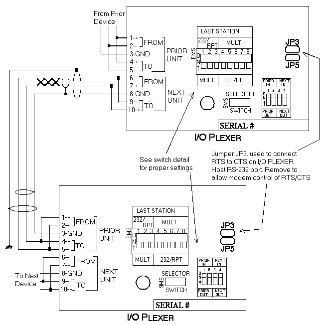
Figure 2-14 shows one individually shielded, twisted pair of AWG 24 with an overall isolated shield (such as Beldon 8162) with the internal shield connected between unit grounds. The overall isolated shield should be connected to earth ground in one place only. In a perfect world with no electrical noise and equal ground potentials everywhere, the signal ground connection would not be required. Not connecting signal ground, however, frequently leads to costly debugging.
These connections, which require the cover plate to be removed, are made by placing a 1/4 inch stripped wire into the openings of the black wire clamp terminal block, and tightening the screw. This block is socketed for easy removal. An alternative means for interconnection is to use the 10-pin male connector located behind the clamp terminal block. This connector mates withMolex shell, 50-57-9005, and female pins, 16-02-0103.
In addition to the I/O PLEXER-to-I/O PLEXER wiring, the installer should confirm that the Network Type switches are set in the correct positions, Multidrop, Repeat, or Last Unit. Refer to Appendix A for details concerning the switches marked "PULL-UP" in figure 2-5.
 |
Figure 2-14 RS-485 I/O PLEXER to I/O PLEXER Wiring
| duTec 6979 Wales Road Northwood, OH 43619 |
800-248-1632 Phone 419-666-4700 Phone 419-666-4702 Fax |
[ Home ] [ Products ] [ Data Sheets ] [ Support ] [ FAQ ] [ Request Catalog ] [ Sales Offices ]
© Copyright 1996-2000, duTec. All rights reserved.
For feedback on this site, please send email to:
webmaster@dutec.net