[ duTec Home ] [ I/O
PLEXER Hardware Manual Table of Contents ] [
Back - Chapter 1 ] [
Next - Chapter 2b ]
Installation
Mounting:
In a wall mounted enclosure the I/O PLEXER can be mounted
horizontally or vertically. Horizontal installation is good practice,
as it makes the best use of natural convection.
Figure 2-1 below, shows the outline of the I/O PLEXER.
Using the keyhole slots, the unit can be mounted with 2 - #10 screws
on 16.5" centers. Using the corner holes, the unit can be mounted with
4 - #6 or #8 round head or pan head screws located on a 3.5" x 16.5"
grid. Hole locations in relation to the overall dimensions are shown
below. Both the I/O PLEXER and the Digital Expander have
the same mounting dimensions.
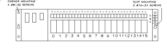
Figure 2-1 I/O PLEXER Footprint
Power Wiring:
Power connections are made at the 3 position terminal block located
on the right end of the I/O PLEXER. No. 8 captive wire
clamps accept 10-16 AWG wire or spade lugs. The terminal block cover need
not be removed to install wiring.
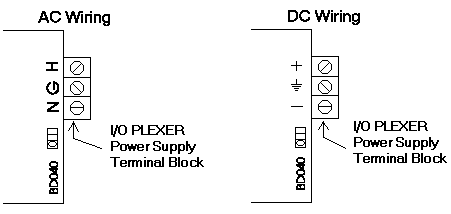
Figure 2-2 Power Wiring
The center terminal block position, adjacent to the letter G on the
end of the I/O module board, is chassis/earth ground, which is connected
to the I/O PLEXER case.
Following power wiring conventions (AWG):
-
Standard 85-132 Vac, 47-440 Hz and Option /E5 105-265Vac 47-440 Hz
Operation:
-
black wire to the terminal marked H (hot)
-
white wire to the terminal marked N (neutral)
-
green wire to the terminal marked G (chassis/Earth ground)
-
Option /B or /C 10-30Vdc Operation:
-
+ of the power source to the terminal marked H
-
- of the power source to the terminal marked N
-
Earth ground, where available, to the terminal marked G
Digital Expander:
The I/O PLEXER Digital Expander (IOP-DE) receives its
power and signals from the I/O PLEXER via the included 24-pin
keyed ribbon cable (duTec Part No. CE-24). No other power wiring is required.
See Figure 2-15
for diagram of multiple installation of Digital Expanders.
Designing the Network
In order for the I/O PLEXER to share its data with
the Host computer, it must be linked via a serial connection. This link
can be hard-wired using an RS-232 link (less than 50 ft.), or an RS-422/485
twisted pair connection where the wire run between devices is less than 5000
feet. In situations where distances are greater than 5000 feet, or circumstances
do not allow additional wire to be installed; RS-232 radio or telephone modems
may be used. In any event, the appropriate transmitter of the I/O
PLEXER will be connected to a suitable receiver of the
Host computer, as shown in Figure 2-3.
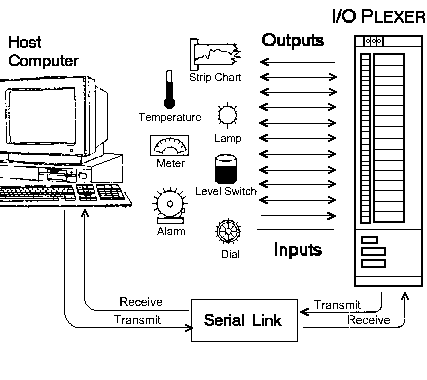
Figure 2-3 Typical Installation
Multiple I/O PLEXER Master chassis can be networked
together to service large numbers of I/O points.
The serial communication link between a Host computer and
a network of I/O PLEXERs can use various combinations of three
wire shielded RS-232, dual twisted pair (plus recommended grounded shield)
RS-422, or single twisted pair (plus recommended grounded shield)
RS-485.
The Host-to-First I/O PLEXER can be any of the three,
but because most Hosts come equipped with an RS-232 port. This is used most
often providing the distance is less than 50 feet. For greater distances,
up to 5000 feet, a choice must be made to either equip the Host
with an RS-422 or RS-485 card, or use an external RS-232 range
extender, such as duTec
BAUDMASTER.
If the Host-to-first unit link is RS-232, the balance of
a network, if any, can be a mixture of RS-422 and/or
RS-485.
If the Host-to-first unit link is either RS-422 or RS-485, the balance
of the network, if any, can be a mixture of RS-422 and/or RS-485.
For total wire runs less than 5000 feet, but RS-422 and RS-485 networks
can operate in Multidrop mode. In this configuration, every unit attached
to the Host computer is passively connected to the network. The benefit
to this is that the loss of power to any unit on the network does not
affect the ability of other units to respond to the Host computer.
A drawback to this approach is that the total length of a
Multidrop segment can only be 5000 feet.
For ranges greater than 5000 feet, some or all of the I/O
PLEXERs can operate in the Repeat mode. In this mode,
the unit plays an active roll in broadcasting the communication signals.
The length of each network segment connected to a unit in the Repeat mode
can be up to 5000 feet. The limitation of the Repeat mode is that a
power failure of any single unit disables communication for all units further
'downstream' from the Host.
Once the physical network media has been chosen, a decision as to
which units, if any, will play an active roll in signal
transmissions. This is to say, whether the unit will re-broadcast, or
repeat signals which it does not originate.
Figure 2-4 illustrates the possible networks that can be created by
specifying Multidrop, or Repeat functionality for an individual
unit.
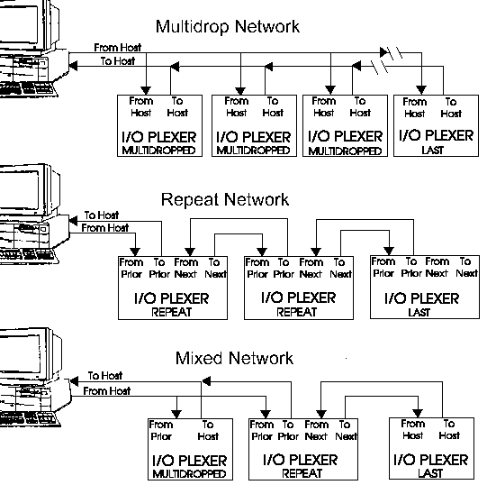
Figure 2-4 I/O PLEXER Network Types
Network Type Switches
Based upon the selected network configuration, each I/O
PLEXER must be setup before communication can begin. This
is done with the network switches shownin figure 2-5.
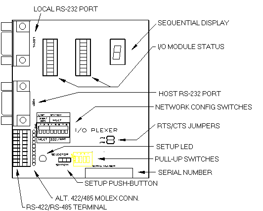
Figure 2-5 Connectors, Switches, and Indicators
The three choices for communication connections for I/O
PLEXER are:
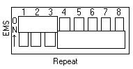 |
Repeat
Used in RS-422, or RS-485 networks to extend range to 5000 feet
between segments. Also used for RS-232 Host-to-First unit link if < 50
feet. Sequential display reads L1 |
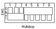 |
Multidrop
Used in RS-422 or RS-485 networks. Provides a total network segment
range of 5000 feet. Sequential display reads L2 |
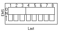 |
Last Unit
Must be used in RS-422 and RS-485 networks for the unit most distant
from the Host. Sequential display reads L3 |
If there is only one I/O PLEXER in a network,
it is designated as a Last Unit.
For the network layout the sequential display indicates the letter
L, followed by 1, 2, or 3. As shipped, I/O
PLEXER are setup as L3, Last Unit. This change is not
part of the push button sequence. The displayed value changes from L1 to
L2 or L3 only after the dip switches under the cover have been set, and the
unit has then undergone a power cycle.
Communication Wiring
Host to I/O PLEXER - RS-232:
Figure 2-9 RS-232 Host to I/O PLEXER
Wiring
Host-To-I/O PLEXER RS-232 communication is limited
to a distance of 50 feet (when distances of greater than 50 feet
are encountered the Host must be equipped with an RS-422/485 device). The
connector for the Host cable, marked Host RS-232 (see figure 2-5),
is a 9 pin female D submin. Pin assignments for this connector may also
be found on the edge of the cover.
The Host connection may be a 9 or 25 pin D submin connector, depending
on whether the AT or XT convention is used. A duTec cable can be used
for this purpose (IOPN-AT, IOPN-XT, or IOPN-AXT).
In addition to the Host-to-I/O PLEXER wiring, the installer
should confirm that the Network Type switches are set in the RS-232/RPT
poositions, and that both CTS/RTS jumpers are in the horizontal position
as shown. The switches marked "PULL-UP" in figure 2-5 should be left
in the "ON" position.
Modem to I/O PLEXER - RS-232:
Figure 2-10 Link via Modem
Two handshake control lines are provided on the I/O
PLEXER for interfacing to modems. They are Request-To-Send
(RTS) and Clear-To-Send (CTS). An active high RTS signal from the
I/O PLEXER advises the modem that data is available. When
the modem is ready to accept data, it places its CTS line active
high to the I/O PLEXER, thus, initiating the data
exchange.
In addition to the modem-to-I/O PLEXER wiring the installer
should confirm that JP3 (the RTS/CTS jumper) is positioned as shown
in figure 2-10. Jumper JP5 (RTS/CTS for the Local RS-232 port) should
remain in the horizontal position unless the RTS/CTS pair is needed in the
device connected to the Local RS-232 port. A cable for most modem
applications, the IOP-RT cable, is available from duTec.
The switches marked "PULL-UP" in figure 2-5 should be left in the
"ON" position.
Note: If the modem must make use of the
RTS/CTS hardware handshake, only one I/O PLEXER can be
used per modem. If more than one I/O PLEXER is used at
a given remote site, care should be taken that the modem does not need RTS/CTS
handshaking, or external hardware will be required.
Host to I/O PLEXER - RS-422:
Figure 2-11 RS-422 Host to I/O PLEXER
Wiring
The wiring figure shows two individually shielded twisted pairs of
AWG 24 (such as Beldon 9729) with the shields connected between unit grounds.
In a perfect world with no electrical noise and equal ground potentials
everywhere, the ground connection is not required. Not using the ground
connection can lead to costly debugging.
These connections, which require the cover to be removed, are made
by placing a 1/4 inch stripped wire into the openings of the wire clamp terminal
block and tightening the screw. This block is socketed for easy removal.
An alternative means for network connection is to use the 10-pin male
connector located behind the clamp terminal block. This connector mates with
Molex shell, number 50-57-9005, and uses pins 16-02-0103.
In addition to the Host-to-I/O PLEXER wiring, the installer
should confirm that the Network Type switches are set in the correct
positions, Multidrop, Repeat or Last Unit. Refer to Appendix A for details
concerning the switches marked "PULL-UP" in figure 2-5.
Host-to-I/O PLEXER - RS-485:
Figure 2-12 RS-485 Host to I/O
PLEXER Wiring
The wiring figure shows one shielded, twisted pair of AWG 24 (such
as Beldon 9841, or 9341) with the shield connected between unit grounds.
In a perfect world with no electrical noise and equal ground potentials
everywhere, the ground connection is not required. Not using the ground wir
can lead to costly debugging.
These connections, which require the cover to be removed, are made
by placing a 1/4 inch stripped wire into the openings of the wire clamp terminal
block and tightening the screw. This block is socketed, for easy
removal. An alternative means for network connection is to use the
10-pin male connector located behind the clamp terminal block. This connector
mates with Molex shell, number 50-57-9005, and uses pins 16-02-0103.
As shown in Figure 2-12, the + terminals of To and From, and
the - terminals of the To and From are connected. These connections
should not be made in the clamping terminal block or Molex connector alone.
A combination of the two can be used, one for jumpering, and the other
for the incoming and outgoing connections. Another option is to use an
external terminal block, or leads between the clamp terminal block and Molex
connectors.
In additon to the Host-to-These connections, which require
the cover to be removed, are made by placing a 1/4 inch stripped wire into
the openings of the wire clamp terminal block and tightening the screw. This
block is socketed for easy removal. An alternative means for network
connection is to use the 10-pin male connector located behind the clamp
terminal block. This connector mates with Molex shell, number 50-57-9005,
and uses pins 16-02-0103. wiring, the installer should confirm that
the Network Type switches are set in the correct positions, Multidrop,
Repeat, or Last Unit. Refer to Appendix A for details concerning the
switches marked "PULL-UP" in figure 2-5.
I/O PLEXER-to-I/O PLEXER - RS-422:
Figure 2-13 RS-422 I/O PLEXER to I/O
PLEXER Wiring
Figure 2-13 shows to individually shielded twisted pairs of AWG
24 with an overall isolated shield (such as Beldon 8162) with the internal
shield connected between grounds. The overall isolated shield should be connected
to earth ground, in one place only. In a perfect world with no electrical
noise and equal ground potentials everywhere, the signal ground connection
would not be required. Not connecting signal ground, however, frequently
leads to costly debugging.
These connections, which require the cover plate to be removed,
are made by placing a 1/4 inch stripped wire into the openings of the black
wire clamp terminal block, and tightening the screw. This block is socketed
for easy removal. An alternative means for interconnectio is to use the 10-pin
male connector located behind the clamp terminal block. This connector mates
with molex shell, 50-57-9005, and female pins, 16-02-0103.
In addition to the I/O PLEXER-to-I/O
PLEXER wiring, the installer should confirm that the Network
Type switches are set in the correct positions, Multidrop, Repeat, or Last
Unit. Refer to Appendix A for details concerning the switches marked "PULL-UP"
in figure 2-5.
I/O PLEXER-to-I/O PLEXER - RS-485:
Figure 2-14 RS-485 I/O PLEXER
to I/O PLEXER Wiring
Figure 2-14 shows one individually shielded, twisted pair of AWG 24
with an overall isolated shield (such as Beldon 8162) with the internal shield
connected between unit grounds. The overall isolated shield should be connected
to earth ground in one place only. In a perfect world with no electrical
noise and equal ground potentials everywhere, the signal ground connection
would not be required. Not connecting signal ground, however, frequently
leads to costly debugging.
These connections, which require the cover plate to be removed, are
made by placing a 1/4 inch stripped wire into the openings of the black
wire clamp terminal block, and tightening the screw. This block is socketed
for easy removal. An alternative means for interconnection is to use
the 10-pin male connector located behind the clamp terminal block. This connector
mates withMolex shell, 50-57-9005, and female pins, 16-02-0103.
In addition to the I/O PLEXER-to-I/O
PLEXER wiring, the installer should confirm that the Network
Type switches are set in the correct positions, Multidrop, Repeat, or
Last Unit. Refer to Appendix A for details concerning the switches
marked "PULL-UP" in figure 2-5.
Adding Digital Expanders:
Up to three Digital Expanders may be connected to any I/O
PLEXER which is equipped with a "/3+" option (click here
for information). These chassis are attached to the main unit via a ribbon
cable supplied with the Digital Expander. Normally, power is supplied through
this cable. In some circumstances, however, the Digital Expander is purchased
with an optional power supply. If so equipped, the installer must provide
the necessary power connections as well
(see Digital
Expanders).
Figure 2-15 Digital Expanders
Digital Expanders are configured during the main chassis' normal setup
procedure (see Chapter 3 -
Setup ).
Continue to Chapter
3
duTec
6979 Wales Road
Northwood, OH 43619 |
800-248-1632 Phone
419-666-4700 Phone
419-666-4702 Fax |
Top of Page
[ duTec Home ] [ I/O
PLEXER Hardware Manual Table of Contents ] [
Back - Chapter 1 ] [
Next - Chapter 2b ]
© Copyright 1996-2000, duTec. All rights reserved.
For feedback on this site, please send email to:
webmaster@dutec.net