Mounting
Power Wiring
Communicating with BASIC I/O
- Multidrop
- Repeat
- RS-422
- RS-485
RS-485 programming
BASIC I/O Hardware User Manual
Chapter 2a - Mounting
BIO4, BIO8 and BIO16 (not AD) Products
[ duTec Home ] [ BASIC I/O Table of Contents ] [ Back - Ch 1 ] [ Next - Ch 2b ]
 |
Mounting Power Wiring Communicating with BASIC I/O
RS-485 programming |
BASIC I/O Hardware User ManualChapter 2a - MountingBIO4, BIO8 and BIO16 (not AD) Products |
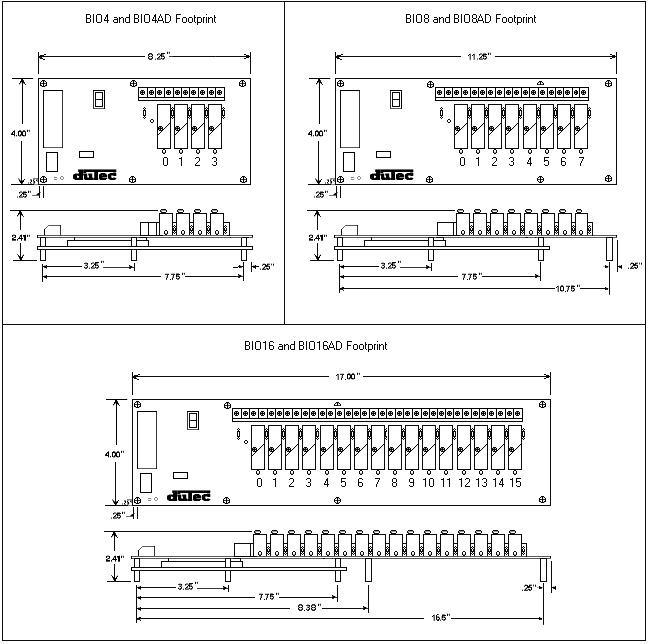
BASIC I/Os come in 4, 8, and 16 channel versions. Figure 2-1 below shows the footprint of each BASIC I/O. Using the corner holes, the unit can be mounted with 4 - #6 or #8 round head or pan head screws. The BIO16 version has two additional mounting holes located near the center of the board as well. Hole locations in relation to the overall dimensions for each are shown below. Since the same BASIC I/O boards are used for digital or analog applications, the same mounting dimensions and panel space are used for both.

Figure 2-1 BASIC I/O Footprint
[Top of Page ] [ duTec Home
] [ BASIC I/O Table of Contents
] [ Back - Ch 1 ] [
Next - Ch 2b ]
Power connections are made at the 2 position terminal block located on the module board marked +5V and GND No. 8 captive wire clamps accept 10-16 AWG wire or spade lugs.

Figure 2-2 DC Power Wiring
| Power Wiring Conventions | ||
| + of the power source to the terminal marked +5V - of the power source to the terminal marked GND |
||
Power Requirements |
||
| Voltage: | 5.0 - 5.4V | |
| Current: | 250mA + 25mA Per digital module or 250mA + 200mA per Analog
module. Note that the current draw of some specialized digital modules, such as the IDC5S or The IDC5Z, can be substantially larger than 25mA. Consult the specific module data sheet for this value when sizing power supplies. |
|
| Practices: | In general it is good practice to reserve the +5V
power supply exclusively for the task of powering one
or more units. As with any microprocessor based
equipment, reasonably clean power is required for reliable
operation. Sharing power with other devices such as field signal transducers and contact excitation should be strictly avoided. |
|
[Top of Page ] [ duTec Home ] [ BASIC I/O Table of Contents ] [ Back - Ch 1 ] [ Next - Ch 2b ]
The BASIC I/O is designed to serve as an intelligent I/O front-end for a Host computer (typically a PC). The Host and communicate over a serial link. This interchange is half-duplex in nature; that is to say the Host and BASIC I/O will never be transmitting at exactly the same time. Further, the communications protocol is considered "speak-only-when-spoken-to"; the Host must poll the BASIC I/O whenever it needs fresh data. This polling is accomplished when the Host sends an instruction to the BASIC I/O. The BASIC I/O will then generate a reply. Each valid instruction will elicit a corresponding response. The integrity of this communication is verified using message content checksums.
The serial communication is in the form of ASCII printable characters and makes heavy use of the hexadecimal numbering system. The format of the ASCII characters used is: one start bit, eight data bits, one stop bit, and no parity.
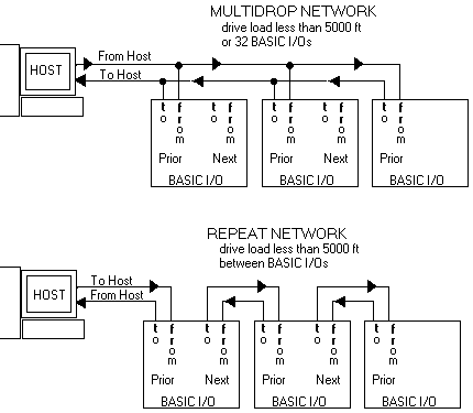
BASIC I/Os can be networked together to obtain up to 4096 I/O points of data. These serial networks can be either multidrop or repeat.

Figure 2-3 Multidrop vs. Repeat Networks
[Top of Page ] [ duTec Home ] [ BASIC I/O Table of Contents ] [ Back - Ch 1 ] [ Next - Ch 2b ]
| Multidrop: | Multidrop networks can be up to 5000ft long end-to-end.
Each station is passively located on the network and represents one "Drop" or load to the host communication driver. A multidrop network will tolerate the loss of power to any one station without effecting the rest of the network. RS-485 can only be multidrop. Signal boost may be necessary depending upon line conditions and number of drops. |
| Repeat: | Repeat networks can be as long as 5000ft between each unit.
Each station plays an active roll in communications to other units. If power is removed from a unit in a Repeat network, communications to units "downstream" from the host will be lost as well. |
The serial communication link between a Host computer and a network of BASIC I/Os is made up of either a single (RS-485 half duplex) or dual (RS-422 full duplex) shielded twisted pair(s) of wires whose shield(s) are connected to a signal common conductor. This communication link should in turn have an overall shield which is isolated from the signals (including signal ground) and connected to Earth or Chassis ground at one location. The most common cause of difficulty experienced by customers in the field is improperly installed communication wiring.
| RS-422 | Advantages
|
Disadvantages
|
|
| RS-485 | Advantages
|
Disadvantages
|
[Top of Page ] [ duTec Home ] [ BASIC I/O Table of Contents ] [ Back - Ch 1 ] [ Next - Ch 2b ]
The BASIC I/O will work equally well when connected to either RS-422 or RS-485; however, special Host programming considerations may be necessary when implementing an RS-485 network.
Unlike RS-422 where both the Transmit Receive signals have their own differential pair of conductors, RS-485 utilizes only one differential pair. The single pair of conductors is used bidirectionally and handles both the Transmit and Receive signals. In order for this to be possible, the transmitter for each device on this type of network must be enabled and disabled whenever a transaction between devices is to take place. The BASIC I/O has been designed to handle this control automatically; however, the transmitter control for most popular RS-485 cards that are installed in the Host computer must be controlled by the user program. This control is not straight forward and may impact the overall system throughput with inherent delay periods.
The following is a typical instruction/response transaction between a Host computer and a BASIC I/O using RS-485:
This interaction is heavily dependent upon asynchronous timing. Usually, the Host software has no real means of determining that the instruction has been completely sent. This means that the program must calculate the approximate time necessary to transmit the entire instruction before the RS-485 driver is disabled. Since the BASIC I/O can respond very quickly to the instruction, the host must disable the driver as soon as possible in order to receive the BASIC I/Os' response. To cope with this dilemma, the host can configure the BASIC I/O to delay a short period of time before transmitting it's response.
RS-485 communication can be tricky at best, and should be seriously considered before being adopted. Third party software users should be certain the package they have chosen supports the particular RS-485 communication card to be used.
duTec
6979 Wales Road
Northwood, OH 43619
800-248-1632 or 419-666-4700
Copyright 1996-2000, duTec. All rights
reserved.
Please contact
webmaster@dutec.net with any questions regarding this
site.