[ duTec Home ]
[ BASIC I/O Table of Contents ]
[ Back - Ch 2a ] [
Next - Ch2c ]
 |

Communication Wiring
-
Network load vs. Noise suppression
-
Network Bias Resistors
-
RS-422 Host to BASIC I/O
-
BASIC I/O to BASIC I/O RS-422
-
RS-485 Host to BASIC I/O
-
BASIC I/O to BASIC I/O RS-485
(multidrop only)
|
BASIC I/O Hardware User Manual
Chapter 2b - Communication Wiring
BIO4, BIO8 and BIO16 (not AD) Products |
COMMUNICATION WIRING
The Host-to-First BASIC I/O can be RS-422 or RS-485. Most Host computers
come aquipped with an RS-232 serial port. A choice must be made to either
equip the Host with an RS-422 or RS-485 card, or use an
external RS-232 to RS-422/485 converter.
For ranges less than 5000 feet, both RS-422 and RS-485 networks can
operate in multidrop mode. For ranges greater than 5000 feet, RS-422 (not
RS-485) networks can operate in the Repeat mode. In this mode, the distance
between individual units can be up to 5000 feet. The trade-off for using
the Repeat mode is that the powering down of any single unit disables
communication with all units further "downstream" from the Host.
A network of BASIC I/Os must be made up of units which are configured
as either ALL multidrop or ALL repeat.
Network Load vs Noise Suppression:
In order to improve RS-485 Bus noise immunity, particularly under
tri-state conditions, a pair of "Network Bias Resistors" have been installed
in each BASIC I/O unit. This design feature has been implemented in order
to satisfy the majority of our customers. If it is necessary to multidrop
more than eight BASIC I/O units (but ultimately less than 32 devices), it
will be necessary to remove these network bias resistors so as not to exceed
the maximum bus loading. However, in order to retain noise immunity, the
network bias resistors should remain installed in at least one BASIC I/O
on the network. Figure 2-3 below shows the location of the four network bias
resistors.
-
R34 is the 1.5k FROM PRIOR + bias resistor
-
R35 is the 1.5k FROM PRIOR - bias resistor
-
R36 is the 1.5k FROM NEXT + bias resistor
-
R37 is the 1.5k FROM NEXT - bias resistor
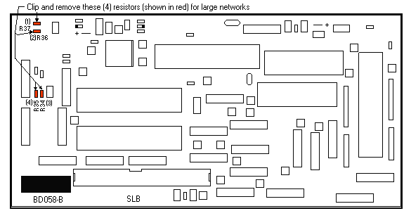
Figure 2-4 Network Bias Resistor Locations
RS-422 HOST-TO BASIC I/O
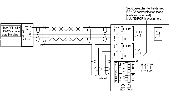
Figure 2-5 RS-422 Host-To-BASIC I/O Wiring
Figure 2-5 shows two individually shielded twisted pairs of AWG 24.
Each pair has a drain wire connected to it's shield. These drain wires are
then connected to the signal grounds at each unit. A separate shield encases
the entire cable. The drain wire for this over-all shield is tied to earth
ground at one location. An example of acceptable wire for this application
would be Belden 8162. In a perfect world with no electrical noise and equal
ground potentials everywhere, the ground connection is not required; however,
omitting this signal ground in industrial applications can lead to costly
debugging.
These connections are made by placing a 1/4 inch stripped wire into
the openings of the wire clamp terminal block and tightening the screw. This
terminal block will accept wire gauges from 14 AWG to 30 AWG.
An alternative means for network connection is to use the 10-pin male
connector located behind the clamp terminal block. This connector mates with
Molex shell, number 50-57-9005, and uses pins, 16-02-0103. In addition to
the Host-to-BASIC I/O wiring, the installer should confirm
that the Network Type switches are set in the correct position: Multidrop,
Repeater, or Last Unit.
[Top of Page ]
[ duTec Home
] [ BASIC I/O Table of Contents
] [ Back - Ch 2a ] [
Next - Ch2c ]
BASIC I/O-TO-BASIC I/O RS-422 Multidrop
or Repeater
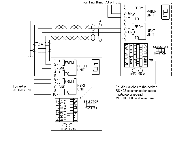
Figure 2-6 RS-422 BASIC I/O-to-BASIC
I/O Multidrop
Figure 2-6 shows two individually shielded twisted pairs of AWG 24.
Each pair has a drain wire connected to it's shield. These drain wires are
then connected to the signal grounds at each unit. A separate shield encases
the entire cable. The drain wire for the over-all shield is tied to earth
ground at one end. An example of acceptable wire for this application would
be Belden 8162. In a perfect world with no electrical noise and equal ground
potentials everywhere, the ground connection is not required. Omitting this
signal ground in industrial applications can lead to costly debugging.
These connections are made by placing a 1/4 inch stripped wire into
the openings of the wire clamp terminal block and tightening the screw. This
terminal block will accept wire gauges from 14 AWG to 30 AWG.
An alternative means for network connection is to use the 10-pin male
connector located behind the clamp terminal block. This connector mates with
Molex shell, number 50-57-9005, and uses pins, 16-02-0103.
In addition to the BASIC I/O to
BASIC I/O wiring, the installer should confirm that the Network
Type switches are set in the correct position: Multidrop, Repeater, or Last
Unit.
NOTE: The number of BASIC
I/Os that can be networked in a Multidrop configuration before a signal
amplifier (an external repeater) is needed depends greatly upon external
factors. Repeater networks are unlimited.
[Top of Page ]
[ duTec Home
] [ BASIC I/O Table of Contents
] [ Back - Ch 2a ] [
Next - Ch2c ]
RS-485 HOST-TO-BASIC I/O
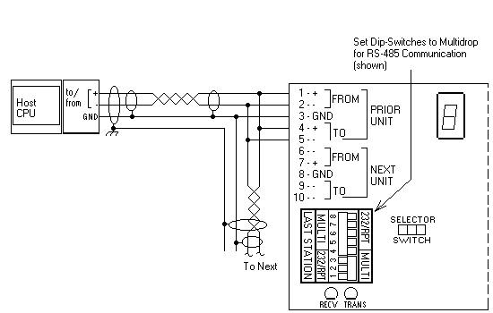
Figure 2-7 RS-485 Host-To-BASIC I/O
Figure 2-7 shows one individually shielded twisted pair of AWG 24.
There is a drain wire connected to it's shield. This drain wire is then connected
to the signal grounds at each unit. A separate shield encases the entire
cable. The drain wire for the over-all shield is tied to earth ground at
one end. An example of acceptable wire for this application would be Belden
8162 (using only one of the two twisted pairs). In a perfect world with no
electrical noise and equal ground potentials everywhere, the ground connection
is not required. However, omitting this signal ground in an industrial
application can lead to costly debugging.
These connections are made by placing a 1/4 inch stripped wire into
the openings of the wire clamp terminal block and tightening the screw. This
terminal block will accept wire gauges from 14 AWG to 30 AWG.
An alternative means for network connection is to use the 10-pin male
connector located behind the clamp terminal block. This connector mates with
Molex shell, number 50-57-9005, and uses pins, 16-02-0103.
In addition to the Host-to-BASIC I/O wiring, the installer
should confirm that the Network Type switches are set in the correct position:
Multidrop, or Last Unit.
[Top of Page ]
[ duTec Home
] [ BASIC I/O Table of Contents
] [ Back - Ch 2a ] [
Next - Ch2c ]
BASIC I/O-TO-BASIC I/O RS-485 (multidrop
only)
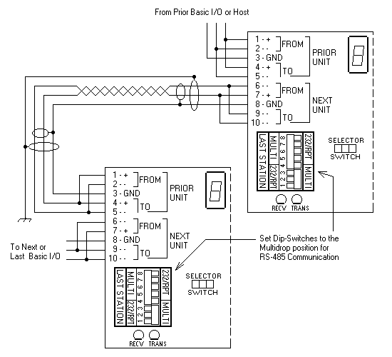
Figure 2-8 RS-485 BASIC I/O-To-BASIC
I/O Multidrop:
Figure 2-8 shows one individually shielded twisted pair of AWG 24.
This pair has a drain wire connected to it's shield. this drain wire is then
connected to the signal grounds at each unit. A separate shield encases the
entire cable. The drain wire for the over-all shield is tied to earth ground
at one end. An example of acceptable wire for this application would be Belden
8162 (using only one of the two twisted pairs). In a perfect world with no
electrical noise and equal ground potentials everywhere, the ground connection
is not required. However, omitting this signal ground in an industrial
application can lead to costly debugging.
These connections are made by placing a 1/4 inch stripped wire into
the openings of the wire clamp terminal block and tightening the screw. This
terminal block will accept wire gauges from 14 AWG to 30 AWG.
An alternative means for network connection is to use the 10-pin male
connector located behind the clamp terminal block. This connector mates with
Molex shell, number 50-57-9005, and uses pins, 16-02-0103.
In addition to the BASIC I/O-to-BASIC
I/O wiring, the installer should confirm that the Network Type switches are
set in the correct position: Multidrop or Last Unit.
The number of BASIC I/Os that can be networked
in a Multidrop configuration before a signal amplifier (an external repeater)
is needed depends greatly upon external factors. Repeater networks are
unlimited.
[Top of Page ]
[ duTec Home
] [ BASIC I/O Table of Contents
] [ Back - Ch 2a ] [
Next - Ch2c ]
duTec
6979 Wales Road
Northwood, OH 43619
800-248-1632 or 419-666-4700
Copyright 1996-2000, duTec. All rights
reserved.
Please contact
webmaster@dutec.net with any questions regarding this
site.


