
BASIC I/O AD Hardware User Manual
BIO4AD, BIO8AD and BIO16AD Products
| [ Home ] [ Table of Contents ] [ Back - Chapter 1 ] [ Chapter 2b ] [ Chapter 3 ] [ Contact duTec ] | |
|
|
BASIC I/O AD Hardware User Manual |
Chapter 2a
BIO4AD, BIO8AD and BIO16AD Products |
Mounting
BASIC I/O ADs come in 4, 8, and 16 channel versions. Figure 2-1 below shows the footprint of each BASIC I/O AD. Using the corner holes, the unit can be mounted with 4 - #6 or #8 round head or pan head screws. The BIO16AD version has two additional mounting holes located near the center of the board as well. Hole locations in relation to the overall dimensions for each are shown below.
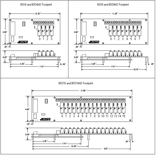
Figure 2-1 BASIC I/O AD Footprint
Power Wiring |
|
| Power connections are made at the 2 position terminal block located on the module board marked +5V and GND. No. 8 captive wire clamps accept 10-16 AWG wire or spade lugs. | |
| Power wiring conventions | |
| + of the power source to the terminal marked +5V | |
| - of the power source to the terminal marked GND | |
| Power requirements | |
| Voltage | 5.0 - 5.4 VDC |
| Current | 250mA + 25mA per digital module and 200mA per analog module. |
| Practices | In general it is good practice to reserve the +5VDC power supply exclusively for th task of powering one or more of the BASIC I/O AD units. As with any microprocessor based equipment, reasonably clean power is required for reliable operation. Sharing power with other devices such as field signal transducers and contact excitation should be strictly avoided. |
In order for the BASIC I/O AD to share its data with the Host computer, it must be linked via a serial connection. This link can be hard-wired, using an RS-422 dual twisted pair, or an RS-485 single twisted pair connection where the wire run between devices is less than 5000 feet. In any event, the appropriate transmitter of the BASIC I/O AD will be connected to a suitable receiver of the Host computer. Multiple BASIC I/O AD chassis can be networked together to serve large numbers of I/O points. These serial networks can be either multidrop or repeat.
| Multidrop | Multidrop networks can be up to 5000 feet long end-to-end. Each station is passively located on the network and represents one "Drop" or load to the host communication driver. A multidrop network will tolerate the loss of power to any one station without affecting the rest of the network. RS-485 can only be multidrop. Signal boost may be necessary depending upon line conditions and number of drops. |
| Repeat | Repeat networks can be as long as 5000 feet between each unit. Each station plays an active role in communications to other units. If power is removed from a unit in a Repeat network, communications to units "downstream" from it will be lost as well. |
| RS-422 Advantages | Easier to implement in software since host driver need not be
controlled. Can be either multidrop or repeat. No turn-around delay required. |
| RS-422 Disadvantages | Requires five conductor wire instead of three. |
| RS-485 Advantages | Needs only three conductor wire. |
| RS-485 Disadvantages | Host 485 driver control must be implemented requiring tricky serial power
manipulations. Can only be multidrop. Usually requires turn-around delay implementation. |
The BASIC I/O AD will work equally well when connected to either RS-422 or RS-485. However, special Host programming considerations may be necessary when implementing an RS-485 network.
Unlike RS-422, where both the Transmit and Receive signals have their own different pair of conductors, RS-485 utilizes only one differential pair. The single pair of conductors is used bidirectionally, and handles both the Transmit and Receive signals. In order for this to be possible, the transmitter for each device on this type of network must be enabled and disabled whenever a message is to be sent. The transmitter for the BASIC I/O AD is designed to handle this control automatically; however, the transmitter control for most popular RS-485 cards that are installed in the Host computer must be controlled by the user program. This control is not straight forward, and may impact the overall system throughput with inherent delay periods.
The following is a typical instruction/response transaction between a Host computer and a BASIC I/O AD using RS-485:
1. |
The Host computer enables it's RS-485 transmitter (usually via the RTS signal line). |
2. |
The Host then sends an instruction to the BASIC I/O AD in the form of an ASCII printable string. |
3. |
Once the Host determines that the string has been completely sent, the RS-485 transmitter is disabled. |
4. |
Every BASIC I/O AD on the network receives the instruction and begin to decode it. The particular BASIC I/O AD addressed begins to construct a response. |
5. |
Once the Carriage Return of the instruction is received, the BASIC I/O AD begins to transmit the response. |
6. |
The Host receives the response and takes the appropriate action. |
This interaction is heavily dependent upon asynchronous timing. Usually, the Host software has no real means of determining that the instruction has been completely sent. This means that the program must calculate the approximate time necessary to transmit the entire instruction before the RS-485 driver is disabled. Since the BASIC I/O AD can respond very quickly to the instruction the host must disable the driver as soon as possible in order to receive the BASIC I/O ADs' response. To help cope with this dilemma, the host can configure the BASIC I/O AD to delay a short period before transmitting it's response. RS-485 communications can be tricky at best and should be seriously considered before being adopted. Third party software users should make sure that the package they have chosen supports the particular RS-485 communication card to be used.
The Host-to-First BASIC I/O AD can be RS-422 or RS-485. Most Host computers come equipped with an RS-232 serial port. A choice must be made to either equip the Host with an RS-422 or RS-485 card, or to use an external RS-232 to RS-422/485 converter, such as duTec's BAUDMASTER.
For ranges less than 5000 feet, both RS-422 and RS-485 networks can operate in multidrop mode. For ranges greater than 5000 feet, RS-422 (not RS-485) networks can operate in the Repeat mode. In this mode, the distance between individual units can be up to 5000 feet. The trade-off for using the Repeat mode, is that the powering down of any single unit disables communications with all units further 'downstream' from the Host.
A network of BASIC I/O ADs must be made up of units which are configured as either all multidrop or all repeat.
In order to improve RS-485 Bus noise immunity, particularly under tri-state conditions, a pair of "Network Bias Resistors" have been installed in each BASIC I/O AD unit. This design feature has been implemented in order to satisfy the majority of our customers. If it is necessary to multidrop more than eight BASIC I/O AD units (but ultimately less than thirty two devices), it will be necessary to remove these network bias resistors so as not to exceed the maximum bus loading. However, in order to retain noise immunity, the network bias resistors should remain installed in at least one BASIC I/O AD on the network. Figure 2-2 below, shows the location of the four network bias resistors.
R34 is the 1.5k FROM PRIOR + bias resistor
R35 is the 1.5k FROM PRIOR - bias resistor
R36 is the 1.5k FROM NEXT + bias resistor
R37 is the 1.5k FROM NEXT - bias resistor
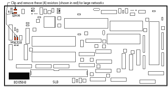
Figure 2-2 Network bias resistor locations
Based upon the selected network configuration, each BASIC I/O AD must be setup before communications can begin. This is done with the network switches, shown below in Figure 2-3.
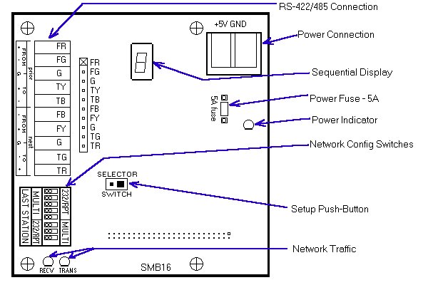
Figure 2-3 Connectors, Switches, and Indicators
The three choices for communication connections for BASIC I/O ADs are:
| Repeat
Used in RS-422 Networks |
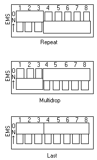 |
| Multidrop
Used in RS-422 or RS-485 networks. |
|
| Last Unit
Must be used in RS-422 and RS-485 |
If there is only one BASIC I/O AD in a network it is designated as a Last Unit.
For the network layout, the sequential display indicates the letter L followed by 1, 2, or 3. As shipped BASIC I/O ADs are setup as L3, Last Unit. This change is not part of the push button sequence. The displayed value changes from L1 to L2 or L3 only after the dip switches under the cover have been set and the unit has then undergone a power cycle.
[ Home ] [ Table of Contents] [ Back - Chapter 1] [ Chapter 2b ] [ Chapter 3] [ Contact duTec ]
The duTec logo, and BASIC I/O AD are trademarks of duTec.
The information contained in this manual is believed to be correct.
However, duTec assumes
no responsibility for any of the circuits described herein, conveys no license
under any patent
or other right, and makes no representations that the circuits are free from
patent infringement.
duTec makes no representation or warranty that such applications will be
suitable for the use
specified without further testing or modification.
duTec general policy does not recommend the use of its products in
life support applications where
the failure or malfunction of a component may directly threaten life or injury.
It is a Condition of Sale
that the user of duTec products in life support applications+ assumes all
the risk of such use
and indemnifies duTec against all damage.
duTec
6979 Wales Road
Northwood, OH 43619
800-248-1632 or 419-666-4700
Copyright 1996-2000, duTec. All rights reserved.
Please contact
webmaster@dutec.net with any questions regarding this site.