[ Home ] [
Products ] [
Data Sheets ] [
Support ] [
FAQ ] [
Sales Offices ] [
Request Catalog ] [
Contact duTec ]


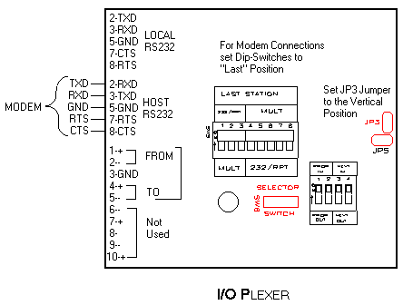
Figure 2-10 Link via Modem
Two handshake control lines are provided on the I/O PLEXER for interfacing to modems. They are Request-To-Send (RTS) and Clear-To-Send (CTS). An active high RTS signal from the I/O PLEXER advises the modem that data is available. When the modem is ready to accept data, it places its CTS line active high to the I/O PLEXER, thus, initiating the data exchange.
In addition to the modem-to-I/O PLEXER wiring the installer should confirm that JP3 (the RTS/CTS jumper) is positioned as shown in figure 2-10. Jumper JP5 (RTS/CTS for the Local RS-232 port) should remain in the horizontal position unless the RTS/CTS pair is needed in the device connected to the Local RS-232 port. A cable for most modem applications, the IOP-RT cable, is available from duTec.
The switches marked "PULL-UP" in figure 2-5 should be left in the "ON" position.
Note: If the modem must make use of the RTS/CTS hardware handshake, only one I/O PLEXER can be used per modem. If more than one I/O PLEXER is used at a given remote site, care should be taken that the modem does not need RTS/CTS handshaking, or external hardware will be required.
| duTec 6979 Wales Road Northwood, OH 43619 |
800-248-1632 Phone 419-666-4700 Phone 419-666-4702 Fax |
[ Home ] [ Products ] [ Data Sheets ] [ Support ] [ FAQ ] [ Sales Offices ] [ Request Catalog ] [ Contact duTec ]
© Copyright 1996-2000, duTec. All rights reserved.
For feedback on this site, please send email to:
webmaster@dutec.net