
I/O PLEXER Hardware Manual
Chapter 3 - Setup
[ duTec Home ] [ I/O PLEXER Hardware Manual Table of Contents ] [ Back - Ch 2b ] [ Next - Appendices ]
|
|
I/O PLEXER Hardware ManualChapter 3 - Setup |
Setup |
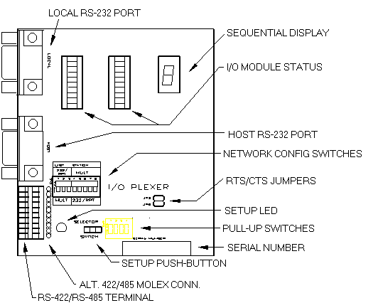
Figure 3-1 Connectors, Switches, and Indicators
During the setup phase of an I/O PLEXER system, the main chassis are given specific values for unit address, network baud rate, and protocol pass type. A momentary push-button and seven-segment display provide access to these parameters. Figure 3-1 shows the location of these components labeled Setup Push-Button and Sequential Display.
Each Host instruction includes an address made up of two hexadecimal characters (00H to FFH). At any I/O PLEXER network connection up to 6 different types of functions can be performed, each with its' own unique system-wide function address. The address for functions which are not present in a particular chassis is set equal to the Master address, so as not to occupy valid space. There are two I/O PLEXER addressing modes, OFFSET and VARIABLE.
Units are shipped in the OFFSET mode where only the Master Unit Control address needs to be set (with a range of 00H to 3FH). The remaining active function addresses are automatically calculated and set based on the Master address.
Function |
Abbrev | Function Address |
Sequential Display |
|---|---|---|---|
| Master Unit Control | MC | 00H (0) | U0=00 |
| Master Unit Digital I/O | MD | 40H (64) | U1=40 |
| Master Unit Analog I/O*** | MA | 80H (128) | U2=80 |
| 1st Digital Expander*** | D1 | C0H (192) | U3=C0 |
| 2nd Digital Expander*** | D2 | D0H (208) | U4=d0 |
| 3rd Digital Expander*** | D3 | E0H (224) | U5=E0 |
The OFFSET addressing mode is more convenient to use as only one address setup is required for each network connection. For example, changing the Master Unit Control, MC from 00H to 03H will automatically cause MD=43H; MA=83H; D2=D3H; D3=E3H.
Variable Mode
In the VARIABLE mode function addresses are independent of each other, and can range from 00H to FFH. For this mode, each function, MC, MD, MA d1, D2, and D3 must be entered. As long as addresses are not duplicated, they can take on any of the 256 possibilities. The VARIABLE mode must be used with some software packages, and systems of more than 16 I/O PLEXER network connections.
The loading of selected function addresses into the I/O PLEXER is explained after the description of Baud rates, and protocol handshake type found in "Changing Setup Parameters via pushbutton:.
Any one of the standard baud rates of 300, 600, 1200, 2400, 4800, 9600, 19200, or 38400 can be used for the serial network communications. The sequential display indicates the letter H followed by the Baud Rate, divided by 100. As shipped, I/O PLEXERS are setup for 9600 Baud; the sequential display indicates H096. Changing the Baud Rate is described in "Changing Setup Parameters via pushbutton:.
Two protocol handshake types are available, 2 Pass and 4 Pass:
| 2 Pass | The Host transmits an instruction to an I/O PLEXER. If the message is correctly received (ie valid address, instruction type and correct checksum), the I/O PLEXER executes the instruction and returns the letter A and a CR or, where data is to be returned, the letter A followed by the data followed by a two character checksum and ending with a CR. | ||
| 4 Pass | The Host transmits an instruction to an I/O PLEXER. If the message is correctly received (ie valid address, but not necessarily the correct instruction type nor checksum), the I/O PLEXER returns an A followed by the echo of the instruction and does not execute it. If the Host then transmits an E, the command is executed in the same manner as 2 Pass. If the Host transmits any other character to any unit on the network, the instruction is disregarded. |
The sequential display indicates the letter P followed by 2 or 4. As shipped I/O PLEXERs are setup for 2 Pass; the sequential display indicates P2. The actual setting of the Handshake Protocol Type into the I/O PLEXER is detailed beginning at "Changing Setup Parameters via pushbutton:".
The digit after the L in the Sequential Display represents how the network switch under the cover plate is set. See "Network Type Switches" here.
Note: The seven segment display will not reflect a switch position change until power has been cycled to the unit.
If modems are not being used, the jumpers should remain in place, as shipped, in a horizontal position . See "Modem to I/O PLEXER - RS-232" here.
Changing Setup Parameters via Pushbutton:
During setup, the user may need to change the unit address, serial link, baud rate, and protocol pass type. The pushbutton located under the removable cover is used to change these parameters. The pushbutton causes the adjacent red LED to flash each time it is pushed. Any changed values are automatically saved in non-volatile EEPROM.
During the diagnostic test period following the application of power,
the sequential display shows:
GoGoGo![]() . Flashing the pushbutton LED once when the
. Flashing the pushbutton LED once when the
![]() appears, places
the unit in the setup mode. The value of each setup character can be changed,
as they appear in sequence, by pressing the pushbutton. The display will
continue to cycle through the setup sequence until there is a full cycle
with no changes. The I/O PLEXER then stores all values in EEPROM for automatic
use following each power cycle. If desired changes were not implemented
correctly, line power can be recycled and the setup via pushbutton procedure
can be repeated as required.
appears, places
the unit in the setup mode. The value of each setup character can be changed,
as they appear in sequence, by pressing the pushbutton. The display will
continue to cycle through the setup sequence until there is a full cycle
with no changes. The I/O PLEXER then stores all values in EEPROM for automatic
use following each power cycle. If desired changes were not implemented
correctly, line power can be recycled and the setup via pushbutton procedure
can be repeated as required.
Once the unit has been placed in the setup mode, as described above, the value of each setup character shown below, can be changed.
U000H096P2 - Only the underlined digits may be changed.
The 2 digits after U0 indicates the Master Unit Control address; initially set for address 00H - 00.
Note: in the address offset mode, only the Master unit address is set, the other addresses are automatically set 40H above each other (see Offset Mode table, above).
The 3 digits after H show the baud rate (divided by 100); initially set for 1200 Baud - 012.
The 1 digit after P signify the handshake protocol type; initially set for 2 Pass - 2.
The display continues to cycle through this sequence until there is a full cycle, with no changes. The I/O PLEXER then stores all values in EEPROM for automatic use following the next power cycle.
The unit is now in the operational mode, and the sequential display cycle becomes: (Factor default values for an IOP-AD/3+ depicted in this example.)
U0 = 00
U1 = 40
U2 = 80
U3 = C0
U4 = d0
U5 = E0
H012
L3
P2
Address Setup via Network - VARIABLE mode only
Each function address, including the Master Control address, of the I/O PLEXER can be set individually by issuing a special instruction to the current Master control address of that chassis. This "set Variable Address" instruction should be used with caution, as it will change the unit addresses, and save them in the EEPROM (see appendix C, C). Consult the I/O PLEXER protocol manual for details.
In the event that the new addresses become lost, they will appear on the sequential display.
The Pushbutton method can always be used to return to the OFFSET mode.
When the I/O PLEXER is initially turned on, it goes through internal self test. If anything is not correct, the appropriate error code will flash on the sequential display. Try recycling power. If that does not resolve the error condition, please call duTec technical support, at 800-248-1632.
Establishing communication is, without a doubt, the most difficult process encountered when installing an I/O PLEXER system. Every component int he system plays a key role in this function. The following steps should aid in troubleshooting an I/O PLEXER system:
The MAGIC software is provided as a tool to help the user become familiar with the I/O PLEXER instruction set. This program incorporates a menu-driver "step-by-step" approach to building any instruction. Once an instruction is developed, it may be sent to the I/O PLEXER. MAGIC will then report the I/O PLEXERs' response to that instruction, thus completing the Host-I/O PLEXER exchange. In addition to assisting in instruction development and transmission/response, MAGIC will also capture groups of instructions into macros to be sent automatically. These macros can be named and stored for future use, making them handy for system setup and Local Control Functions.
The software may be downloaded here; or if you received a manual, it can be found on 3.5" disk in the back of the manual.
To install this software, create a directory called MAGIC, and copy the contents of the diskette, or download, to that directory.
MAGIC will prompt the user for the communication port (it has been reported that COM3 and COM4 may not behave properly with MAGIC) of the Host computer, the baud rate, and the Master Control address of the I/O PLEXER. Once all this information has been entered, the user is ready to start building instructions, and sending them to the I/O PLEXER.
Note: The MAGIC software has not been revised for some time, and therefore has not been updated with some of the more recent features of the I/O PLEXER. This includes digital expanders 2 and 3.
[ duTec Home ] [ I/O PLEXER Hardware Manual Table of Contents ] [ Back - Ch 2b ] [ Next - Appendices ]
| duTec 6979 Wales Road Northwood, OH 43619 |
800-248-1632 Phone 419-666-4700 Phone 419-666-4702 Fax |
© Copyright 1996-2000, duTec. All rights reserved.
For feedback on this site, please send email to:
webmaster@dutec.net